Millimeters to Inches Chart for Steel Pipe Manufacturing
In the world of steel pipe manufacturing, precision isn’t just a goal—it’s a legal and safety requirement. Whether you are running a mill in Southeast Asia or sourcing structural tubing for a project in North America, you are constantly dancing between two worlds: the metric system and the imperial system.
A “close enough” conversion might work for a backyard fence, but when you are dealing with API or ASTM standards, being off by a few thousandths of an inch can lead to catastrophic pipe failure, rejected shipments, or threading that simply won’t seat. This is where a reliable millimeters to inches conversion chart becomes the most important tool in your shop.
The Standard: Why 25.4 is the Magic Number
In pipe manufacturing, everything revolves around the Outside Diameter (OD) and the Wall Thickness (WT). While most of the world uses millimeters, the US market still demands everything in decimal inches and pipe “schedules.”
The industry standard bridge is exactly 25.4.
Metric to Imperial: mm/ 25.4 = inches
Imperial to Metric: inches times 25.4 = mm
If you’re on the factory floor and need to convert 1.4mm to inches for a thin-walled structural tube, the math gives you 0.055118″. In a manufacturing setting, we usually truncate this to four decimal places: 0.0551″. That tiny number is the difference between a high-quality product and a “second.”
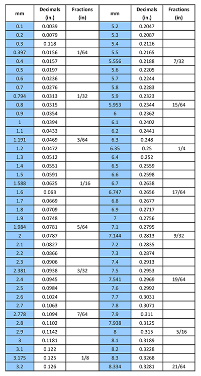
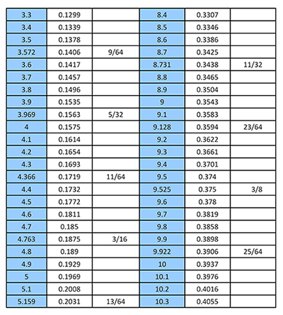
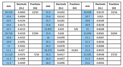
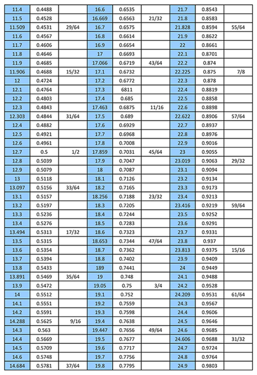
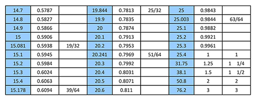
The Precision Conversion Table: Inch-mm Decimal
For steel pipe, we don’t usually use fractions like 1/8″ or 3/16″. Machinists and QC inspectors want the conversion table inch mm-decimal. Fractions are too vague for CNC pipe threading or ultrasonic thickness testing.
The 1.4mm Case Study: Why the Decimal Matters
You might wonder why a manufacturer would specifically care about 1.4mm to inches. In the production of ERW steel tubes, 1.4mm is a very common “sweet spot” for light structural applications, such as furniture frames or automotive exhaust components.
If your client’s blueprint calls for a wall thickness of 0.055″ and your mill is set to produce 1.4mm, you are technically providing 0.0551″. On a single pipe, that 0.0001″ difference is invisible. But if you are shipping 50,000 feet of pipe, that extra thickness adds significant weight to the total order. Since steel is often sold by weight, an inaccurate conversion can throw off your freight quotes and your profit margins.
Wall Thickness and “Gauge” Confusion
In the steel pipe world, the millimeters to inches conversion chart is often complicated by the “Gauge” system. A “14-gauge” pipe isn’t the same everywhere.
In the US, 14-gauge steel is often considered 0.0747″.
However, many international mills will supply a 2.0mm pipe as a substitute, which is actually 0.0787″.
If you rely on a name like “14-gauge” instead of a decimal conversion, you end up with pipes that don’t fit the standard couplings or connectors used in the field. This is why modern manufacturing is moving away from gauge names and toward strict mm-to-decimal-inch specifications.
Tolerance: The Hidden Trap
In manufacturing, no pipe is perfectly 1.4mm. There is always a “tolerance”—usually +/- 10%.
If you convert 1.4mmto 0.055 inches, but your production line drifts to 1.35mm, your actual thickness is now 0.0531inches.
If the project specifications require a minimum of 0.054 inches, your entire batch could be rejected. When using a conversion table inch mm-decimal, always factor in your mill’s tolerance range. Don’t just convert the target number; convert your “floor” and “ceiling” numbers to ensure you stay within the customer’s spec.